Whites SPP Adding Conductivity switch

Prospecting Australia

Help Support Prospecting Australia:

This site may earn a commission from merchant affiliate links, including eBay, Amazon, and others.
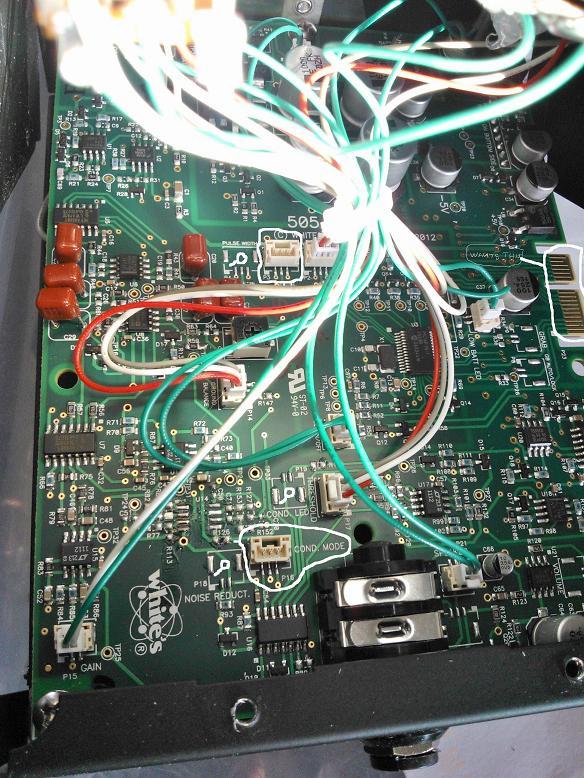
Hi Zuke and All. Here is a photo of the SPP circuit board. I have white circled around the two female plugs. You will note that just above the COND Plug and also to the left of it is a spot for the LED Plug and the Noise Reduction Plug. I have drawn a little white circle with a tiny line to denote these. You will also note the same above where I have outlined the female Pulse Plug. Above that plug reads Pulse Delay To the left of this is my little circle which reads Pulse Width where I assume another plug would be. Its interesting how they have left the COND and PULSE DELAY plugs in place but not the LED... Noise reduction Or PULSE WIDTH Plugs. To the right hand side of the board you will see two connection points...one long and one short with bare brass contacts. I have circled these. Have no idea what they may be. Looks like a way to connect another board in future machines maybe??? Anyway my question to you is.....It looks like a switch could simply be plugged into the Cond. Plug, so would it be worth a try to see what happens.??? Surely it's not going to blow up, is it.??? Tis just a switch. What I know about electronics you could fit on the head of a pin. So I'm no expert, but looking at the rest of the board, it looks very straight forward... Other plugs from the other controls simply plug in to their labelled plugs. What we are obviously not going to get is the three LEDs cause the plug for these is clearly missing. Would need to know which way the three wires would need to go in the switch though. The board number by the way is........505-0255D.
1407123722_circuit_board_2.jpg
 
3 position toggle, 10k pot, You've got yourself an SL.. (in theory)
The pins on the side are for T&E allows whites to plug it in and troubleshoot the machine, also probably program it?..

COND mode isn't worth messing with.. PW might be though..
 
Hi. Lazy Trommel. Only really need the Conductivity switch. That's the one that allows the Discriminating tricks. Are you saying that the switch and Plug is likely to be a simple three way like I could buy from J.CAR or Dick smith.? How do I figure out the three wires? Can I do that by trial and error till it works?
 
basically, the detector is running in one of those modes right now..

If you were to buy a 3 position 3 pol toggle from jaycar..

Ok, centre pin on the board is your common (mode its running in right now) because pins 1 and 3 aren't shorting with 2..

So, you wire pin 2 (centre) to the middle pol on the toggle, pins 1 and 3, to 1 and 3 on the board/toggle..
When you switch to position 1 or 3.. you're creating a short between 2 of the 3 pins, HI, med, Low ..

Its probably that simple, but I'm NOT! saying go ahead and try it.. If you do, its at your own risk.. (sorry just covering my arse lol)
I don't see it doing any damage, but you never know right?

Anyway that's the theory.. maybe some of the other technically minded people on the forum can chip in..
 
Adding to my last post....Just looked at the pics again of Zukes Pro Oz. The switch looks like it is a bit more complicated than just the three wires. I see there are extra pins that also need to be wired with short bits across posts. I'd need to have a map to do that.
 
Yes, Its a DPDT toggle.. I didn't even bother looking at it..

Not sure, pics aren't the best angle of viewing, but the Conductivity socket on the TDI has 4 pins, not 3 like yours.. Or I'm looking at the wrong plug..
And what looks like a single pair of shielded wires(which makes sense), with small diodes across the pols to prevent cross talking..

Then again, its a TDI Pro, not an SL.. So my theory could be correct.
 
With the SPP has anyone had a good look to see what can be done to extend the battery operating hours and charging the batteries from a 12v power source thanks :)
 
Hi Old Hand,
I am thinking of making up a LiPo battery to be used in the SPP there's quite abit of info on how to DIY. The Lipo can be charged via a 12 volt battery around a 1 hour charge time.
 
In regards to the conductivity switch it's as easy as adding a SPST center off switch to the 3 pin plug on the board with no chopping or hacking' other than a hole.
Obviously center pin to center pin' I'll add mine in the next few weeks If ppl want to wait till then' but there shouldn't be any issue as it is the same as the SL.
I'll probably add my switch to the front opposite the coil connector, oh and don't forget your warranty goes west'
 
Zuke_Lynzy said:
In regards to the conductivity switch it's as easy as adding a SPST center off switch to the 3 pin plug on the board with no chopping or hacking' other than a hole.
Obviously center pin to center pin' I'll add mine in the next few weeks If ppl want to wait till then' but there shouldn't be any issue as it is the same as the SL.
I'll probably add my switch to the front opposite the coil connector, oh and don't forget your warranty goes west'

Yeah, 3 pin plug, not much else it could mean.. It'll be interesting to see how it turns out..
 
The pic of the SPP board is the right one. The circled 3 pin connector for the conductivity switch is also correct. My recommendation is to ask the White's distributor to order pre made 3 pin SL connectors with leads attached that will plug into the pc board and simply add the 3 position switch. This is by far easier and shouldn't interfere with the warranty. BTW, the connector is active so all that is needed is to add the switch with the connector connector and plug it in. It works. Been there, done that. BTW, the center pin on the connector connects to the center pin on a 3 position SPST Center OFF Switch. The other two leads go to the other two switch pins. Then it is a matter of mounting the sw such that HI conductor is UP and LOW is down if you want to be consistent with the SL or the TDI operation.

I don't recommend trying to wire the switch to the pc board directly. The center pin on the connector on the pc board is connected to the -5V and the other two pins connect to gates on a 4066 IC.

For those wondering, the audio signal after a particular IC becomes either a positive or a negative signal, depending upon the conductivity of the signal. Since there are two distinct possibilities, you can have either a high or a low tone. When ALL is selected, both tones are summed later in the design, which effectively combines both signals. The down side if this idea is noise from both channels is also summed. Selecting only one tone reduces the noise which is why I recommend selecting one or the other setting when hunting. If both tones are required, I recommend hunting with one and then hunting with the other on a different pass. Fortunately, this discussion as given me another idea to try.

Since Jimmy Sierra is selling these units, maybe he could help in getting the necessary parts if the OZ White's distributor can't get them.

Now, on a different note there is no pulse width feature programmed, so don't worry about that feature and there is no width connector mounted on the pcb. I haven't tried the pulse delay to see if it is active or not with a pot installed but the delay connector is mounted on the pcb.

Finally, getting back to using only a single tone mode, I recommended using only one tone when possible because it does lower the noise and this will help even on the SL.

Reg
 
Welcome to the Oz forum Reg! great to see you as a member, there is always an active topic you might want tune in on at times.

Luke.
 
Just tested the above with a SPTT, works as intended... don't know why anyone would bother though.. still Its an extra function for $1.45 Jaycar..
Subgram is quite pleased with his $1195 PI.. except the pathetic battery life.. which is easily solved..
 
LazyTrommel said:
Just tested the above with a SPTT, works as intended... don't know why anyone would bother though.. still Its an extra function for $1.45 Jaycar..
Subgram is quite pleased with his $1195 PI.. except the pathetic battery life.. which is easily solved..

Can I ask where did you get the plug for PCB socket from?
Karl
 
plug isn't required unless you intend on removing it at some future point..

Soldering iron with a conical tip, solder each wire on, make sure you slip over some heat shrink and you're done..

You could buy the plug, hell you can buy the whole plug/toggle setup from gold search Australia i believe.. I used what i had..
 

Latest posts

Top