condor22
Mike
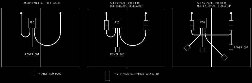
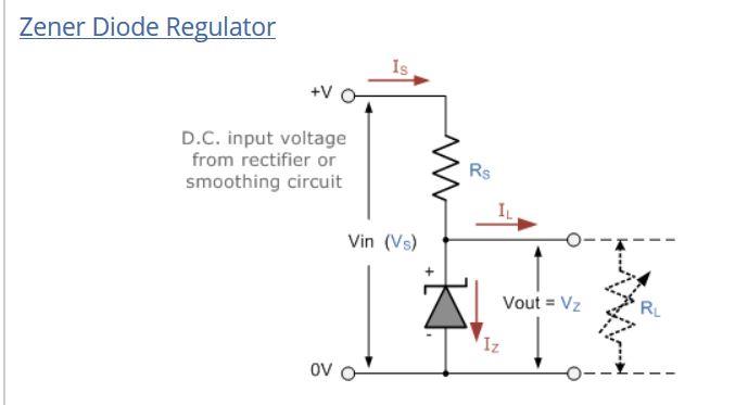
A Zener diodes primary application is to prevent flowback i.e. it only allows current flow in one direction). It's typical application is, when a solar panel is going through a controller to a battery it is charging and flowing in that direction.
At night, you do not want battery power flowing back through the controller to the panel, which it can and will unless a directional control diode is in circuit.
They sometimes can allow reverse flow, but only if the voltage reaches a certain point. So I do not think a Zener diode will limit the voltage in the direction of flow.
If you are still concerned, email Ctek and ask them what might happen if the input voltage exceed the charger/controller's rating...... (go to ctek's web page then click contact, it allows for an email messaging system.)
")