


kleinman98
John Kleinman
- Joined
- Oct 3, 2013
- Messages
- 886
- Reaction score
- 233
Interesting you are using Arduino for this project. I use them for robotics and a homebuilt Segway.
SteelPat said:Marauder said:Thanks for the info guys, I'm pretty set of the Surf PI 1.2, but can't get silverdogs website to work. Stack of SQL errors.
Electronicly speaking ground balance doesn't seem that hard to do with PI, assuming that it doesn't vary greatly over a given area, it should be easy enough to tune out, before the comparators. I'd also like to note here that if i'm talking out my arse feel free to point out.
My Plan is to buy two of the kits and set them up so that the electronics board is interchangeable to that i can mod one board and compare it with the original design. At the moment I'm thinking of adding ground balance(manual) and replacing the components with high precision pieces, to see if it makes a difference.
Also I'll just jump on the Discrimination on PI band wagon and say that i think it would be possible. As far as i understand the PI detector induces current in the target, which creates a magnetic field from the target, which in turn creates a current in the detector coil, which is observable whilst the pulse is inactive. Each type of target should create a different field, depending on the target composition, a different frequency probably, and the amplitude would be determined by size. With a micro controller you could compare these against known types(iron) and reject the signal(not relay the signal to the rest of the detector) ie discrimination. The only problem would being able to do the comparisons at speed. There are specific high speed comparators that are capable of this, but I'm sure its not easy to do in practice.
Electronic ground balance isnt hard in theory - it's the electronics that will let you down. Basic idea is to get a sample with no target present - this is your ground base signal. You then subtract that from the mixed target response (this will contain target response and ground response). Then all that should be left is target. This is good in theory but in practice the ground signal will vary even moving a few cm away. Also you have EF to contend with. This is the signal that the earth itself creates. This too needs to be removed from mixed target response. Then there is EMI - another signal that needs to be removed.
I will post some more tech info on timings for basic GB/EF that I implemented on the MPP (via a ChipKIt Uno board that I wired to basic circuit) that will show you the basics of that. These timings work but the electronics let the thing down a little as they are a bit noisy and not fast enough.
As for the discrimination: With a PI you are not looking at the current created as such - what you are looking at is the decay time after the pulse has been turned off. Yes you are correct, the decay time does change for different materials and the basic idea of comparing it to known decay times will work - BUT - not with the way analogue receive circuits work. And unfortunately thats how most, if not all, kits are done (this goes for a most commercial pi machines too). There is a way around this which I have yet to implement. By using a ADC and taking 1uS (or less) samples straight after pulse turnoff (after any significant EMF if no snubber is in circuit) you can create a sample wave shape. After all EMF/EF and GB have been removed the resultant wave slope could be compared against known materials. This should work but as I said I have yet to implement it. I do have a ARM Cortex4 discovery board all ready for this project - just need time to do it.
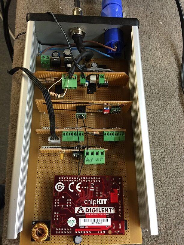
Here is my modded MPP:
https://www.prospectingaustralia.com/forum/img/member-images/4467/1444701561_mpp_mod.jpg
And this is a design of my own thats also controlled by a Chipkit Uno:
https://www.prospectingaustralia.com/forum/img/member-images/4467/1444701595_ccpi.jpg
If you want more technical info ie timings/arduino code etc feel free to ask.
 make sure you double check them capacitor and ic rotations / polarity!
