Relay help please

Prospecting Australia

Help Support Prospecting Australia:

This site may earn a commission from merchant affiliate links, including eBay, Amazon, and others.
Joined
Mar 28, 2014
Messages
25
Reaction score
10
Location
Tumut, NSW
Hi all I am after advice on what relay to use if there is even one out there that will do what I want.
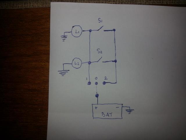
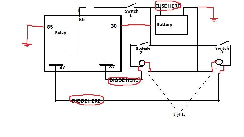
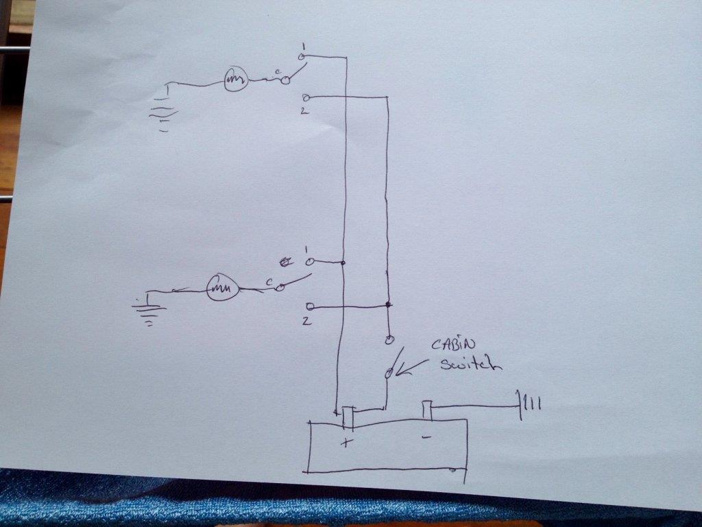
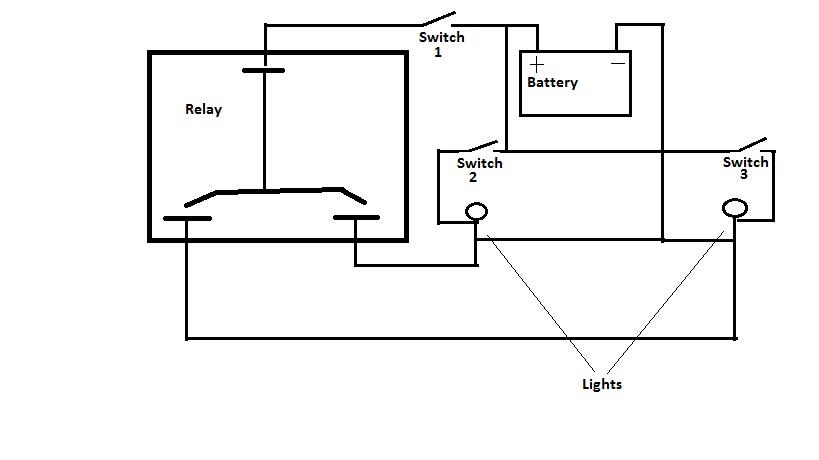
the led flood lights which draw 2.25A each will be mounted on pivoting arms on the rear of the canopy on my ute the plan is to use them for reverse lights that both turn on with one switch in the cab and for flood lights for camping that I can turn on individually with switches on the rear so I need a relay with 2 powered terminals out of it that once turned off have no link between them anyway here is a rough diagram of what I want any help will be greatly appreciated
1420335021_relay_diagram.jpg
 
Mrs dwt suggests you need a couple of 3 pole switches, and wire into a thermal relay, thermal relay for overheating from drawing 2.25amps, but you might need a relay to handle 4.5amps when both switched on.
One 3 pole switch for left light, off, right light.
Second 3 pole switch for both lights on, off, connected to reverse switch.
dwt disclaimer: mrs dwt is not a qualified, or practicing auto sparky, however she was a Electronic Technician on Navy warships,
which means absolutely fark all to me :|
Best of luck to you mate, I'd be dropping your rig into a auto sparky for a day
Whispering....... don't tell someone I said that though!! ;)
 
Here's a simple circuit

1420353712_20150104_170910.jpg


3 Pole Switch -
Position 0 = OFF
Position 1 = Power to both lights and switches 1 & 2 are bypassed
Position 2 = Power to switches 1 & 2 which can then turn 1 or both on & off.

This negates the use of a relay, however one can still be used. Put a 10A fuse between the battery and the 3 pole switch near the battery.
Also put a 5A fuse between switch 1 and its light and the same for the other light.

Be aware of using the correct cable size to handle the current and distance voltage drop.

Unlike DWT's missus, my work was flying around at Mach 2, not leisurely sailing the seas, lol

BTW if you use twin core from the cab 3 pole to the back, even tho, they are red and black, you can use one for pole 1 and the other for pole 2. When I do this, I usually wrap some red insulation tape around the black wire where it is seen.
 
Why not just run 2 normal relays' have no1 relay powered continuously with a neg trip' that way you can flick a toggle switch to earth the relay' turning the lights on without key on.
No2 wired so that its triggerd by the Rev lights "earthing the No1 relay" turning the Lights on with the Rev lights.

But hard to explain but iv done this many times and it's faultless even the relay that has positive power all the time is safe as its contained untill it's tripped' unfortunately you will need to run 1 main power wire to No1 relay but could come from Aux battery if at rear that way the lights won't drain the starter battery if you fall asleep at the fire Pissssed.

Can finger paint a diagram if any wants one.
 
Ryan - The one thing you don't mention is which battery are you using. Or indeed if you have an auxiliary and if so where it is.
 
condor22 said:
Ryan - The one thing you don't mention is which battery are you using. Or indeed if you have an auxiliary and if so where it is.
Hi I will using the aux battery. I did a little more research today and I was thinking a couple of strategically placed rectifier diodes may do the job
 
A rectifier diode limits current flow in one direction. i.e. one use is to stop reverse flow of a battery back to a solar panel, when the panel output drops below the battery voltage at night. It does not act as a switch.
 
Your original sketch uses 3 switches and 1 relay. Using 2 relays means switching 2 relays either with 2 switches, a 3 pole switch or a 2 pole switch operating 1 relay to switch the second. This depends on how you want to do what.......

I prefer the KISS principle, after all, a relay is only an electrically controlled switch and your total load on this circuit is only 4.5A max.

A 3 pole centre off switch is a positive way of directing current to 2 outputs, but only one at a time. This is the main control you need at the driver seat.

Do the lights have inbuilt on/off switches or are these to be add ons?
 
Hi Ryan,

your original sketch shows the relay output connected to the negative side of the lights. Lots of blown fuses that way so I am assuming it is a slip in the drawing.
Use two blocking diodes in your diagram, one on each of the wires from the relay output to the lights, they will do what you want but make sure you get them with a current rating of at least double what your lights are going to draw.

A standard 5 pin relay with two 87 terminals will work just fine. Narva <a href="http://www.narva.com.au/products/browse/normal-open-4-5">68032</a> will be the one.

Wiring diagram needs to look something like this
1420433585_lights.jpg

Hope this helps
 
So S1 activates the relay. I'm assuming that both terms 87 are duel output which when S1 is on, turns on both lights.

When S1 is off, the lights are direct connected to the battery via S2 and S3 and bypass the relay altogether.

In which case why use the relay?

and

If the relay is not energised what do diodes do, to add any value? If S1, 2 and 3 were all on at the same time everything still works anyway.

I refer back to my initial diagram - S1 is the master switch, it allows you to power both lights from the cab, or provide power to S2 and S3 to independently operate from the rear near each light, or isolate everything, saving the expense of a relay and diodes, which for 4.5A are an overkill. Heck a cigarette lighter hits it's wiring with more than double that. Just add fuses.
 
The original post asked the questio, does such a relay exist.
They do and I showed one way to wire that particular relay into Ryan's circuit.
S1 will be the reversing switch in the gearbox and using a relay is a matter of choice or preference.
The diodes are necessary to prevent backfeeding through the 87 contacts of the relay which are always linked
whether the relay is energised or not.

A threeway switch on the dash will need to have its position 1 wired through the reversing switch in the gearbox as well.
It is illegal to have reversing lights that are not switched via the gearbox.
Also there are limits on the light that is emitted by reversing lights, I will look it up the relevant ADR later, but I suspect these will be over the limit.
 
The ADR

Vehicle Standard (Australian Design Rule 1/00 - Reversing Lamps) 2005
- F2005L03873

Link
http://www.comlaw.gov.au/Details/F2005L03873

This ADR applies to lights that ARE connected to the gearbox reversing lights.

However if lights are mounted at the rear and either covered or aimed at the body of the vehicle when driving and are only deployed off road and in a camping environment, I would consider that the ADR does not apply.

Also even if connected to the gearbox reversing lights, an isolating switch would still need to be installed to allow driver control override. Much like my front spotties are connected to high beam, they still have an on/off.

Also, even though there are Commonwealth ADRs, each State has it's own rules re vehicle mods, which should be checked, I would suggest, prior to spending money or putting in any effort to install. Most Auto Electricians will know what is legal and at the end of the day may be the cheaper option.
 
I cannot understand why you would want to use relays and diodes for such a simple circuit. Just wire it like this or how condor has shown.
1420679123_fullsizerender.jpg
 

Latest posts

Top